Reducing WiFi power consumption on ESP8266, part 2

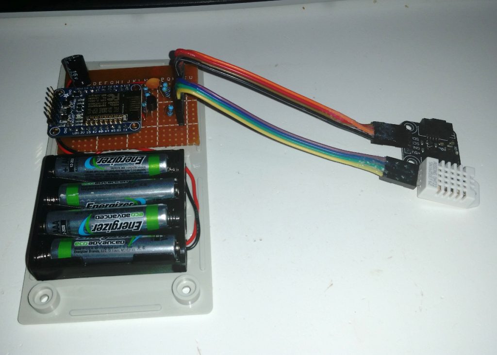
In my previous post I showed the baseline power consumption data for one of my ESP8266-based weather monitors.

The device wakes up from deep sleep, reads some sensors, connects to a WiFi network and transmits the readings over MQTT, it will then go back to sleep for 5 minutes.  One such reporting cycle would consume 0.164 mAh.

This time I’ll show the first steps on the way to reducing this to less than half.

Continue reading “Reducing WiFi power consumption on ESP8266, part 2”

Reducing WiFi power consumption on ESP8266, part 1

The ESP8266 is a brilliant little chip, one I am using for a lot of network connected devices such as weather stations, lighting controllers, environment monitors, etc.

For a lot of these, it is important to be able to run for extended periods on batteries.  Several will be in places where there is no power connections, and I don’t want to run around changing batteries all the time.

After experimenting for a while, I had a weather station which could operate for 3 weeks on 4 AAA batteries.  Not too bad, considering the device had WiFi connectivity and would transmit the current readings back to my server every 5 minutes.  However, it is possible to achieve much better results than this. Continue reading “Reducing WiFi power consumption on ESP8266, part 1”

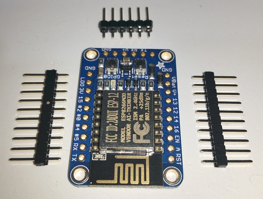
Soldering headers to boards

When buying microcontrollers, breakout boards and the like, they often come without headers.

In order to plug these boards into a breadboard, we’ll have to solder some headers on to them.  Doing so is quite easy.

Most boards have 2.54mm pin spacing, so if your board did not come with headers, you’ll find suitable header strips in almost every electronics shop.  Look for something like this: https://littlebirdelectronics.com.au/products/40-pin-header-terminal-strip

These strips snap off easily to the desired size, just double check that you have the correct number of pins before you snap.  As an example, Adafruit’s Huzzah ESP8266 breakout board have two rows of 10 pins each, in addition to 6 pins for FTDI.

Continue reading “Soldering headers to boards”

Introducing the "Network of things", or… "Notwork"

After having worked in different IT departments for 30 years, one of my standard quips is that our job is to ensure that the network doesn’t turn into a notwork.

Now it seems that there is a new need for that term “Notwork”, and it’s related to the so called “Internet of Things”, or “IoT”.

I have several of these electronic devices around the home, measuring temperature, controlling lights, measuring power consumption, etc., and they all fall under what people will call Internet of Things.

However, not a single one of these devices are on the Internet…  In fact, the wireless network they connect to is not even routed to internet, it is a completely separate network only communicating with my device management server.

So I have decided to call this a Network of things, or Not.  OK, I just know that is not as catchy as internet of things, and I’m going to have a hard time selling the idea of calling it “Not”.  And if I ever start building and selling devices commercially, it is going to be tough convincing people that “notwork” devices actually work…

However, that’s a worry for another day so there it is, I proudly introduce the notwork.

Arduino traffic lights simulator, part 4

Welcome back.

This time I will show the basics of how to connect a push button to the traffic light simulator circuit and how to read it from within an Arduino sketch.  If you haven’t read parts 1, 2 and 3 yet, I recommend you do so first as it will make it easier to follow the examples.

For this demonstration, we’ll use a simple push button like this.  They have four pins, connected together two by two.  Usually the two pins on either side are connected together, and pushing the button will connect them to the two pins on the other side.  If you’re in doubt, use a multimeter to check which pins are connected together.

Additional parts needed this time:

Continue reading “Arduino traffic lights simulator, part 4”