Amiga tank mouse laser conversion – Alternative firmware

I’ve been working on alternative firmware for the Amiga tank mouse conversion that can be found on PCBWay.
Amiga tank mouse

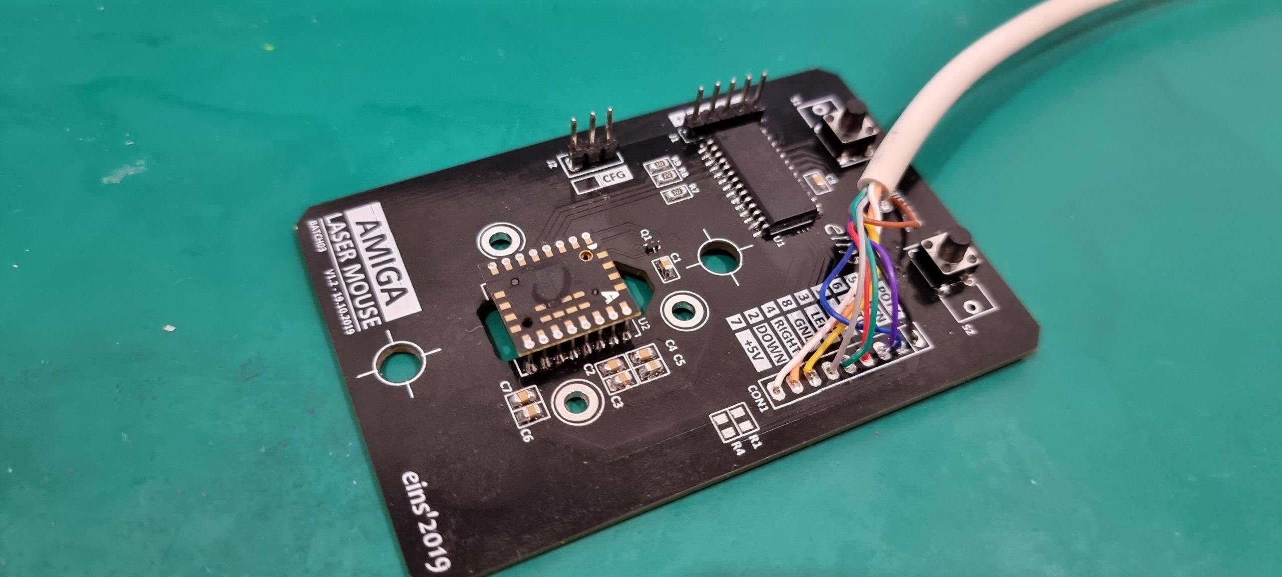
The mouse is using a Microchip PIC18F26K22 MCU and an Avago ADNS9800 optical sensor.
The firmware monitors the ADNS9800 sensor and translates the X/Y movement deltas into V/VQ and H/HQ quadrature pulses for the Amiga

I may be putting the source code up on Github eventually, but for now, here’s a link to download the HEX file.

Continue reading “Amiga tank mouse laser conversion – Alternative firmware”

Solar powered ESP8266

Recently, I added solar power to one of my ESP8266 weather stations.

With the right hardware, this was actually remarkably easy to do.  To make things nice and easy, I ordered an Adafruit USB/DC/Solar Li-Ion/Li-Poly charger.  (Top-right in the photo)  These boards can take DC input from USB, a 2.1mm power jack or from wires soldered directly onto the board.  It will then both charge a Li-poly battery and power a load.  Whatever power is left over from powering the load will be used to charge the battery, and if the load draws more than what the solar panel can provide, the rest will be drawn from the battery.

Continue reading “Solar powered ESP8266”

Electronics basics: Ohm's law

This is a post to explain the basics of electronics, starting with Ohm’s law.

Ohm’s law describes the relationship between the voltage, current and resistance in a circuit, and it is one of the basic physical laws that controls how circuits work.

We need to understand this law in order to select the correct resistors to use in our circuits and to control how much current will flow.  We also need to know how much power our circuit will draw and how much power each component will dissipate.  Too much power and things will heat up too much, burning out.

And yes, this post does contain garden hoses…

Continue reading “Electronics basics: Ohm's law”

Soldering headers to boards

When buying microcontrollers, breakout boards and the like, they often come without headers.

In order to plug these boards into a breadboard, we’ll have to solder some headers on to them.  Doing so is quite easy.

Most boards have 2.54mm pin spacing, so if your board did not come with headers, you’ll find suitable header strips in almost every electronics shop.  Look for something like this: https://littlebirdelectronics.com.au/products/40-pin-header-terminal-strip

These strips snap off easily to the desired size, just double check that you have the correct number of pins before you snap.  As an example, Adafruit’s Huzzah ESP8266 breakout board have two rows of 10 pins each, in addition to 6 pins for FTDI.

Continue reading “Soldering headers to boards”

Arduino traffic lights simulator, part 4

Welcome back.

This time I will show the basics of how to connect a push button to the traffic light simulator circuit and how to read it from within an Arduino sketch.  If you haven’t read parts 1, 2 and 3 yet, I recommend you do so first as it will make it easier to follow the examples.

For this demonstration, we’ll use a simple push button like this.  They have four pins, connected together two by two.  Usually the two pins on either side are connected together, and pushing the button will connect them to the two pins on the other side.  If you’re in doubt, use a multimeter to check which pins are connected together.

Additional parts needed this time:

Continue reading “Arduino traffic lights simulator, part 4”