

Welcome back.
This time I will show the basics of how to connect a push button to the traffic light simulator circuit and how to read it from within an Arduino sketch. If you haven’t read parts 1, 2 and 3 yet, I recommend you do so first as it will make it easier to follow the examples.
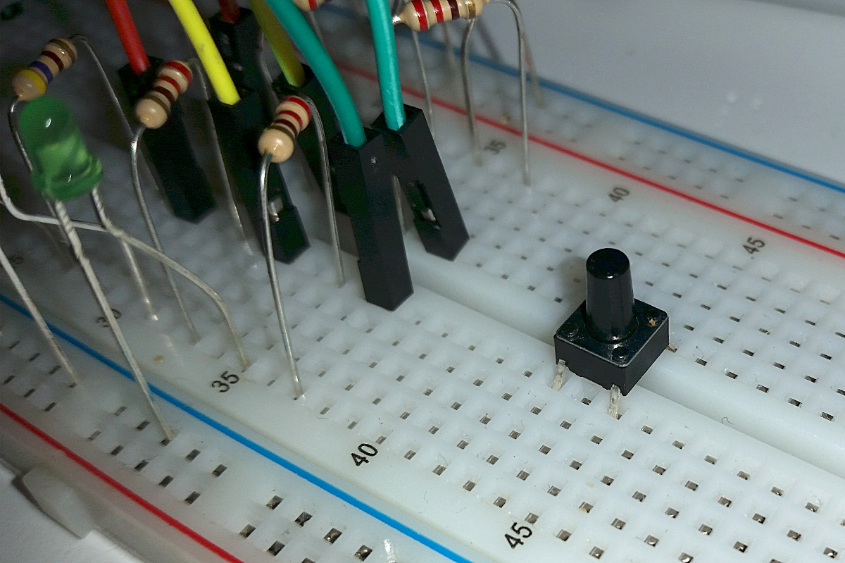
For this demonstration, we’ll use a simple push button like this. They have four pins, connected together two by two. Usually the two pins on either side are connected together, and pushing the button will connect them to the two pins on the other side. If you’re in doubt, use a multimeter to check which pins are connected together.
Additional parts needed this time:
- 1 x Push button, momentary, single pole, single throw (SPST)
- 1 x 10KΩ resistor, 1/4w axial
- 1 x 470Ω resistor, 1/4w axial
- 3 x Breadboard jumper wires
The circuit
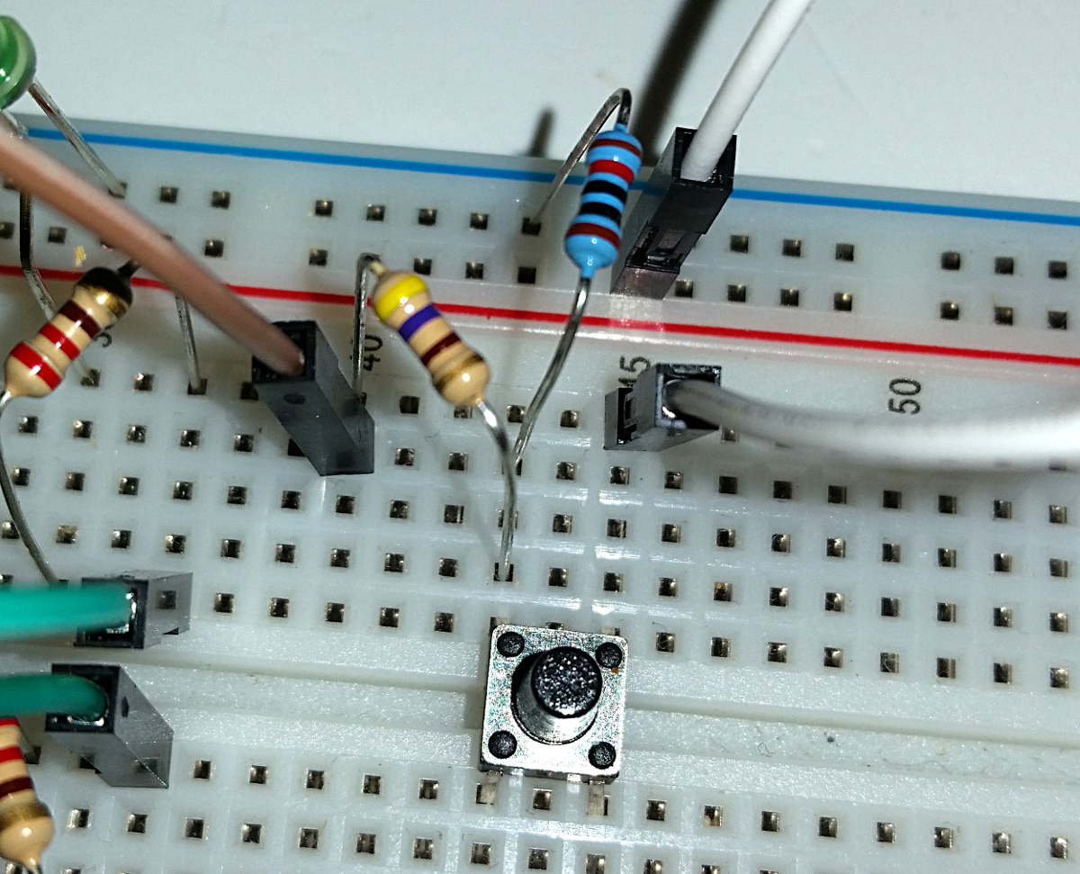
This picture shows the push button plugged into the breadboard. The two pins on the left are connected together, and so are the two on the right. When the button is pushed, it will make contact between the two sides, and thus between rows 43 and 45 on the breadboard. Simple…
Now we need to decide what we want to connect the button to. One side will go to the microcontroller but the other side has to go somewhere, too. For the simplest demonstration, we will connect it either to ground or to +5V. The microcontroller can detect and understand both, so we can choose whichever is most convenient. We’ll choose +5V this time, as what’s going on then is more intuitive.
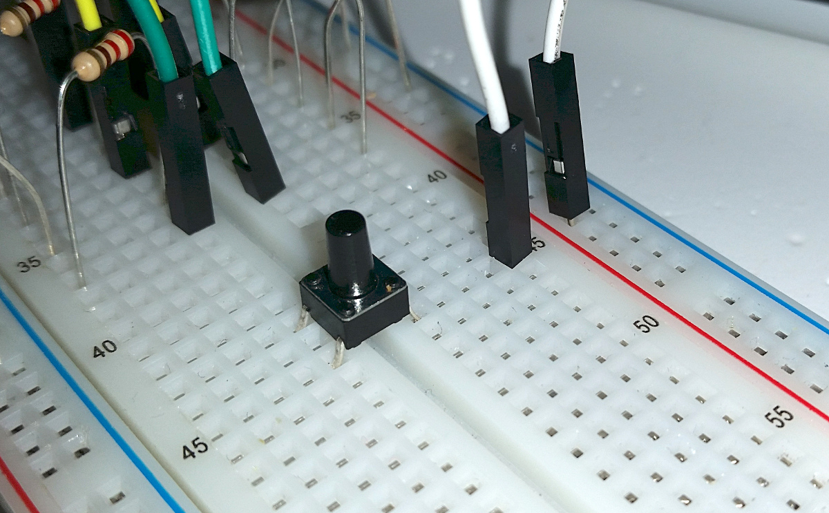
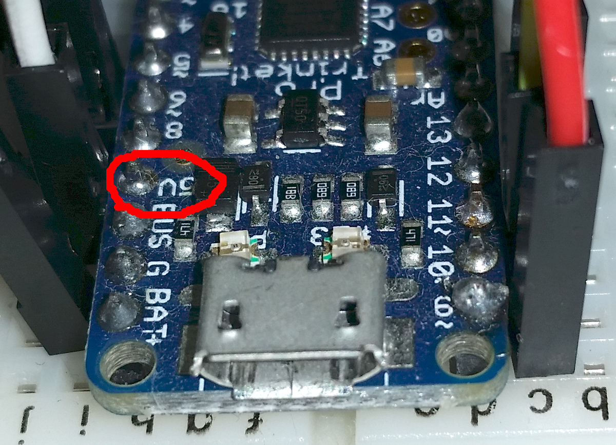
We also have to hook the positive voltage rail up to +5V. The Pro Trinket has a dedicated pin for this. Other microcontrollers will have this in other locations, but pretty near every Arduino compatible will have one. If you are using a 3.3V controller, use that port instead. We could connect the +5V pin directly to the push button, but I find it is a good habit to just send it through the power rail instead. That way it is easily available for any other component we may add which needs +5V.
However, we can’t just connect the other side of the push button directly to a pin on the Pro Trinket. Whenever the switch inside the button is closed, it will connect +5V to the microcontroller, which will see that as a signal. However, when the switch is open, then nothing at all is connected. This is called a floating pin, and results in the microcontroller not being able to get a reliable reading. The reading could be high or low depending on what else is going on inside the chip, whether or not someone is touching any of the wires, the position of the sun and the moon, and pretty much anything else imaginable. If you’re used to databases, it is like a NULL value, neither here nor there. To avoid this, we need to make sure the microcontroller reads a solid low voltage any time the button is not pressed. For that we need a pull-down resistor. That’s not a special type of resistor, but rather a resistor that is used to pull the voltage low. We’ll connect a 10KΩ resistor between the push button and ground.
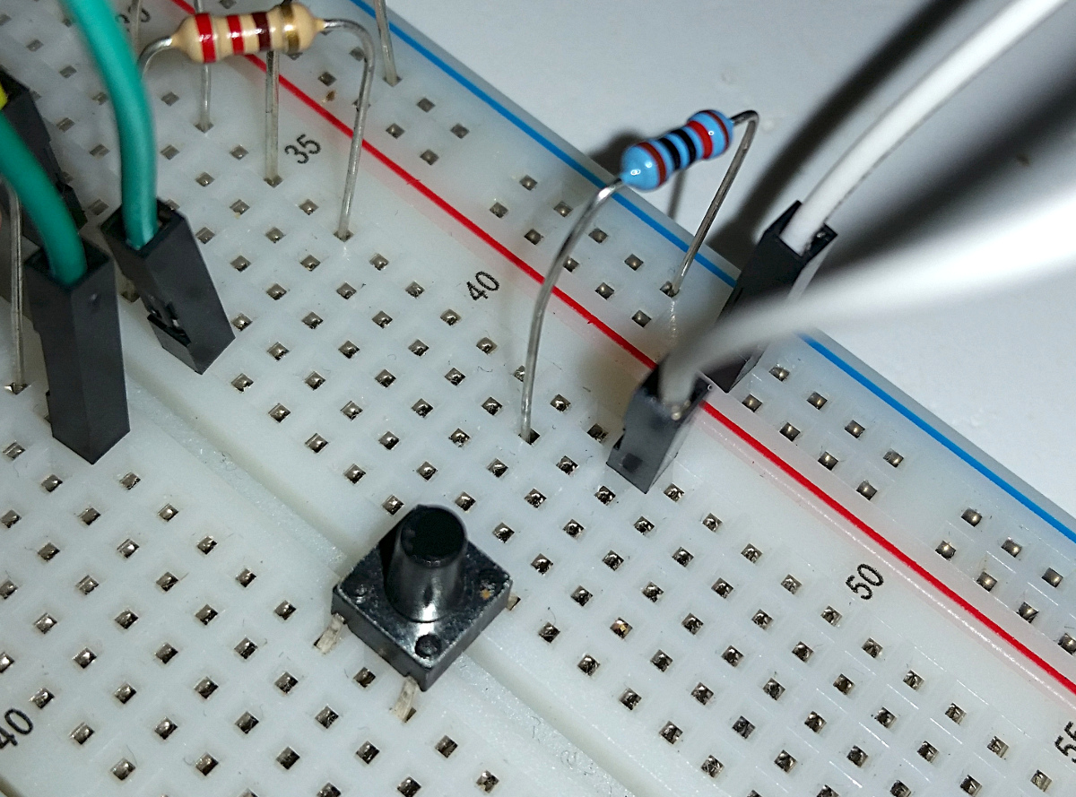
Strictly speaking we don’t NEED the next resistor, but because we’re dealing with a programmable device (the microcontroller), we don’t have a guarantee that the pin we’re connecting to will always be an input. If someone (not us, certainly, but someone… You know…) sets the pin to be an output and writes the pin LOW, we’ll have a bit of a problem when the button gets pressed… There will be +5V going from the power rail, through the button and straight to ground through the microcontroller pin. Not fun… Trust me, the smoke may look pretty but it’s always bad news.
So, to mitigate against this problem, we’ll add a resistor between the button and the microcontroller as well. Arduino and compatible usually have a current limit of 20mA per pin. Pro Trinket follows this, but if you are using a different controller, please confirm with the manufacturer’s documentation and adjust the calculation if necessary.
Remember Ohm’s law, , so
. 250Ω is the lowest value we can use and still be safe. I happen to have a few 470Ω resistors here, so will use one of those.
Finally, we connect a jumper wire between the 470Ω resistor and pin 4 on the microcontroller.
The sketch
We’ll start with the sketch from last time and adapt it a bit to read the push button.
First of all, at the top of the sketch we’ll use a #define to declare that we are using pin 4 to read the push button.
#define BUTTON 4
Next we will configure pin 4 to be an input. Add the following two lines to the bottom of the setup() function:
// Set the button pin to be input
pinMode( BUTTON, INPUT );
So how can we read the button state? It’s easy. Just as digitalWrite() is used to set a pin HIGH or LOW, we can read a pin state with digitalRead(). We’ll read the pin and check if we have a HIGH state. In the loop() function, add this at the beginning of the function:
uint8_t buttonState = digitalRead( BUTTON );

if( buttonState == HIGH )
{
  state++;
  if( state == 6 )
  {
    state = 0;
  }
}
You’ll notice that the code being run if the buttonState is HIGH is the same code as we used to transition to a new state. The result is that we transition to the next state if the button is pressed. Now remove the state change code from further down in the loop() function.
The only thing left at the bottom of the function will be the call to delay(). Without a delay the traffic lights will cycle through all the states when the button is pressed that all the LEDs will appear to be on at the same time. On the other hand, if we leave the delay() as it is now, it could take up to 5 seconds from the button is pressed until the traffic lights change. That’s not a particularly good solution, either.
The solution is to only call delay() if the button is actually pressed, so we’ll put an if-statement around it. We’ll also shorten the delay to half a second (500 ms) so that if you keep the button pressed, the traffic lights will change state twice per second for as long as you keep it pressed.
if( buttonState == HIGH )
{
  delay( 500 ); // Wait half a second
}
Compile and upload, then try the circuit out.