

This is a post to explain the basics of electronics, starting with Ohm’s law.
Ohm’s law describes the relationship between the voltage, current and resistance in a circuit, and it is one of the basic physical laws that controls how circuits work.
We need to understand this law in order to select the correct resistors to use in our circuits and to control how much current will flow. We also need to know how much power our circuit will draw and how much power each component will dissipate. Too much power and things will heat up too much, burning out.
And yes, this post does contain garden hoses…
Ohm’s law
Ohm’s law is usually expressed as , where
is current, measured in Amperes (often just called “Amps”) and with a unit of A.
is the voltage (also called “Electric potential”), measured in Volts and with a unit of V.
is the resistance, measured in Ohms and with a unit of Ω.
This means that with a given voltage, the current that will flow is inversely proportional to the resistance it has to flow through.
Imagine a garden water hose. You open the tap fully and the water will flow, as fast as the hose will allow. The water pressure is like the voltage in a circuit and the flow of water is like the current. Now start squeezing the hose and the flow of water will decrease. Your squeezing of the hose acts as a resistance to the water, and a resistor in an electric circuit works the same way. The harder you squeeze, the less water will flow. The higher the resistance, the less current will flow.
Given any two of the 3 components, voltage, current or resistance, we can calculate the last one. We can rearrange the formula in different ways, depending on what we need to calculate, so you will some times use it as to find the resistance from the voltage and current, or
to find the voltage across a resistance at a certain voltage.
Application with a single resistor
Let’s apply this to a simple circuit with a single resistor: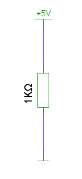
Here we have a known voltage, 5V and a known resistance of 1000Ω (Usually written as 1KΩ, for 1 kilo-Ohm). Putting these numbers into the formula gives us
. 0.005 Amperes is usually written as 5 milliAmperes, or just 5mA. In low-power electronics, we’re dealing with mA most of the time so you’ll get familiar with these units soon enough.
But what do we need resistors for? Can’t we just connect the wires and start having fun?
Practical example, LED
As mentioned in one of my earlier posts, LEDs have a limit to how much current they can safely pass. The more current you send through an LED, the brighter it will glow, but pass the maximum limit and it will burn out, and quite quickly.
To limit the current, we need a resistor connected in series with the LED. This means that the resistor is connected between the LED and either the power source or ground. The same current will flow through all parts of a circuit that are connected in series, so it doesn’t matter which side of the LED you connect the resistor to.
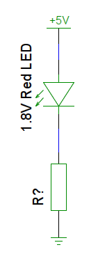
A typical red LED has a forward voltage of 1.8 volts, which leaves 3.2 volts across the resistor. With a maximum current limit for the LED of 20 mA, or 0.020 Amps, we put this into the formula to find the resistance that will give us 20 mA.
. For LEDs, we’ll normally select a resistor that is a bit higher than that, as resistors have a tolerance, for example 5% or 10% accuracy. If our resistor is a 10% tolerance variety, it can be as low as 144Ω and still be within tolerance. However, that 144Ω resistor would allow
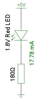
. That might just work, depending on the LED, but it would certainly reduce the life of the LED. By moving up to a 180Ω resistor instead, we’ll be safely within the maximum limit of the LED, and the difference in brightness would be imperceptible to most eyes. According to the same formula, 180Ω gives us a current of
, or 17.78mA.
Another practical example, Arduino current limits
On an AVR-based Arduino you should not exceed 40 mA current in or out of any IO pin. However, this is an absolute, DO-NOT-EXCEED limit, so instead 20 mA is recommended as a limit as it gives a safe margin to the 40 mA, and it reduces any power dissipation issues as well. Remember resistors have tolerances, so always stay clear of such absolute limits.
Imagine a GPIO pin connected directly to 5V:
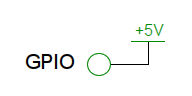
Depending on how the pin gets configured, for example as a LOW output, this lets a nearly unlimited (completely unlimited as far as our poor little chip is concerned…) current flow from +5V, through the GPIO pin and to ground. This could well be the default state of the pin upon startup, meaning this high current will start to flow as soon as power is applied.
This is a fast and easy way to let the magic smoke out of your Arduino, and unfortunately… Arduinos don’t work without the smoke, so once you let it out, the Arduino will stop working. So, to make sure we don’t blow up the chip, we’ll need to add a resistor between the GPIO pin and 5V, to limit how much current can flow. Remember the recommended limit is 20 mA, so we’ll find a resistor that gives us no more than that:
,
. So, any resistor of at least 250Ω will be safe to use, just check the tolerance and make sure you’re still good even at the bottom end of the range. Sticking to common resistor values makes the job of finding a suitable one much easier. 330Ω or 470Ω are very common values, and at 5V they allow 15.15mA or 10.64mA current, respectively.
Note that with a microcontroller like the ones in the Arduinos, they do not need much current in order to detect a signal, and most of the time you do not need much current out of the microcontroller, either, so you will typically use resistors much higher than this, perhaps even 10 or 100 times higher.
Resistors in series
Resistors can be connected in series, which means that you’ll connect two or more of them back to back. The same current will flow through both resistors and will be restricted by both of them. Remember the garden hose. This time you’re squeezing with two hands. This means that the resistance will add up, so a 150Ω and a 470Ω resistor would work the same as a single 620Ω resistor. One important difference, though, is that the two resistors connected in series will have a larger surface area and can thus dissipate more power safely. I will get back to practical applications of this in another post. For now, think of this as an easy way to build resistor values. For example, if you need a 620Ω resistor, but don’t have one (hint: it’s not a standard resistor value…), you can easily build one by connecting a 150Ω and a 470Ω in series.
Looking back at our LED example earlier, let’s see what happens when we place two 180Ω resistors in series with the LED:
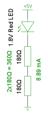
The two resistors add up to 360Ω, which limits the current through the resistors and LED to . 8.89mA is still enough to light up that LED, and the brightness is almost indistinguishable from when we were passing 17.78mA through it. However, this time it’s only using half the power.
Resistors in parallel
Resistors can also be connected in parallel. In that case, the current will be split between them, according to their relative values, and the resulting resistance will be lower than the resistance of the individual resistors.
If it is counter-intuitive that the resistance becomes lower, let’s go back to the garden hose again. You’re holding one garden hose and squeezing it to limit how much water is flowing through it. Now fully open up a second tap, pick up a second garden hose and squeeze exactly as hard as on the first one. How much water is flowing now? Twice as much water as before. That means the current (water current in this case) is twice as large. Remember the formula , in order for the current (I) to be twice as large, the voltage (V) would need to double or the resistance (R) would need to be halved. You haven’t done anything to the water pressure, which is analogous to the voltage, so letting the water run through 2 hoses has effectively halved the resistance.
The same holds true for resistance in a circuit as well, and if you have two parallel resistors of the same value, it is very easy, you end up with half the resistance. For example two 470Ω resistors in parallel will give you 235Ω resistance. The main difference between a single 235Ω resistor and two 470Ω resistors is that in the latter case, the current is split between two resistors, with each passing only half of the current. This results in a lower voltage drop across the resistors, which could be important. This, in turn, also means that there is less power to be dissipated by each resistor.
Let’s go back to the LED example again, but this time put two 470Ω resistors in parallel.
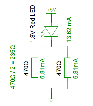
This time, each of the resistors will pass , 6.81mA. There are two of them in parallel, so in total they will pass 13.62mA.
But how about parallel resistors where the resistors are not all the same value?
This is where things start to get complicated. Back to the garden hose… This time you’ve got your whole yard full of garden hoses, and all your friends are coming over to help squeeze them. Problem is, they don’t all squeeze with the same force as you do, so how much water will flow in total? Now, before your whole property gets water damaged, let’s crack this one by considering a general case, and let’s use 1 volt to make the calculation easier:
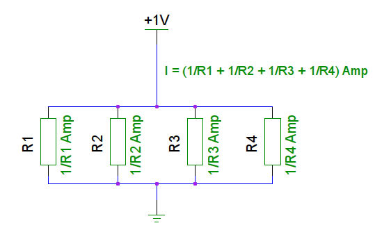
Each of the resistors will pass , and the total will be
To find out what resistance that works out to, we’ll plug this and the voltage into the formula to calculate resistance from voltage and current:
Some good news for you: There will not be a pop-quiz or test at the end of this post. In my next post I will get to some more practical applications of this.