

This is a great little project for learning about Arduino programming as well as LEDs and resistors.
I’ll show how to build a traffic light simulator on a breadboard and write an Arduino sketch to control it. This first part is about building the circuit, while the second part will focus on the sketch.
And: No soldering required.
Parts
You will need the following parts. I’ve provided links to product description pages, in case you’re not sure what to get.
- 1 x Arduino compatible. I’m using an Adafruit Pro Trinket 5V.
- 1 x Solderless breadboard
- 2 x Red 3mm LEDs
- 2 x Yellow 3mm LEDs
- 2 x Green 3mm LEDs
- 6 x 220Ω resistors, 1/4W axial
- 8 x Breadboard jumper wires
Microcontroller
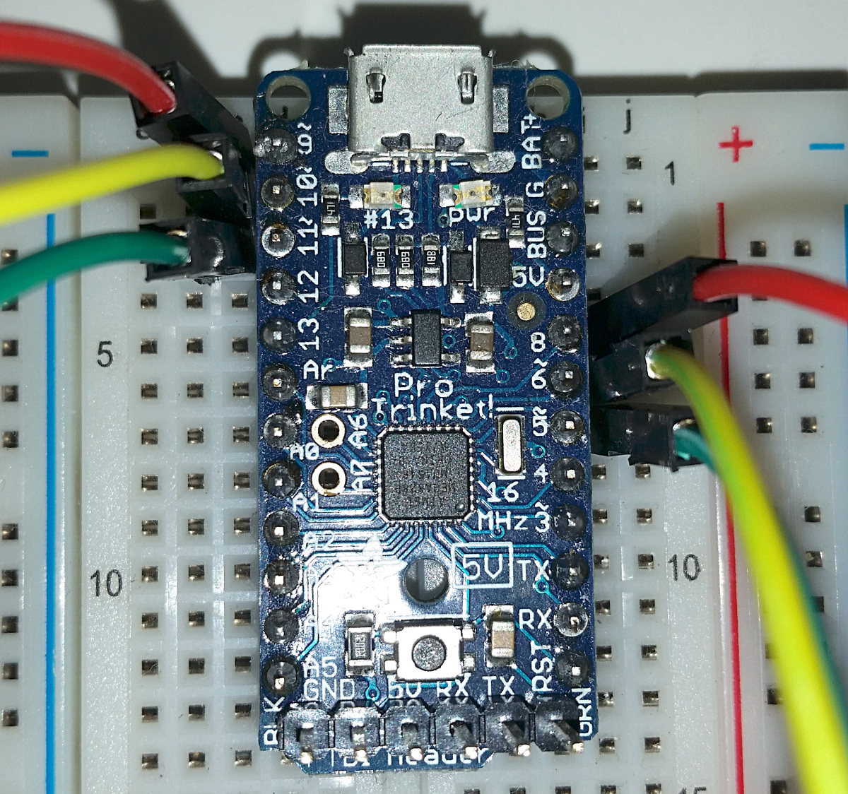
The Pro Trinket is an Arduino compatible microcontroller. It is smaller than the original Arduino Uno and can be plugged directly into a breadboard. That makes it easier to use for this project. If you use a bigger Arduino, you can still follow the instructions, you just have to connect jumper wires from the Arduino to the breadboard instead. However, the instructions and calculations are based on a 5V microcontroller. If you use a 3.3V controller, the resistor value calculations shown below will have to be adapted.

It is small.
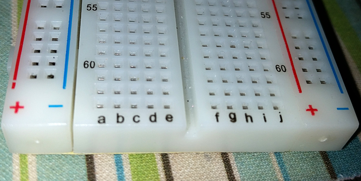
On each row of the breadboard, all the holes in columns A-E are connected together, likewise F-J. There is no connection between E and F.
Connect the Pro Trinket by pushing it into the breadboard, the first set of pins in row 1, but make sure that the two rows of pins go on either side of the groove running down the middle of the breadboard.
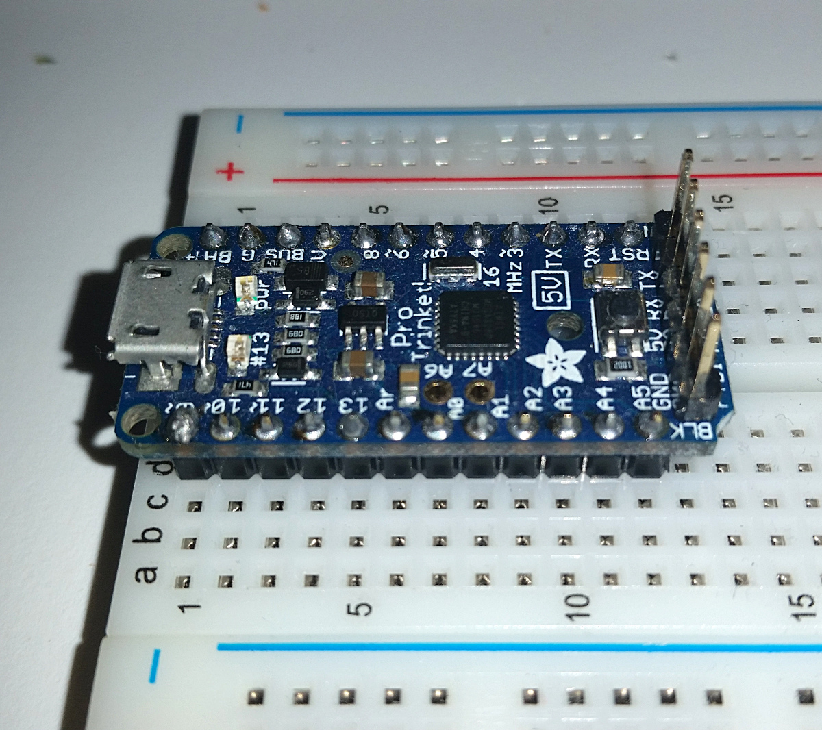
Don’t worry if your controller looks different from this one, the instructions will still work, but with minor adaptations.
LEDs
Next, let’s move on to the LEDs
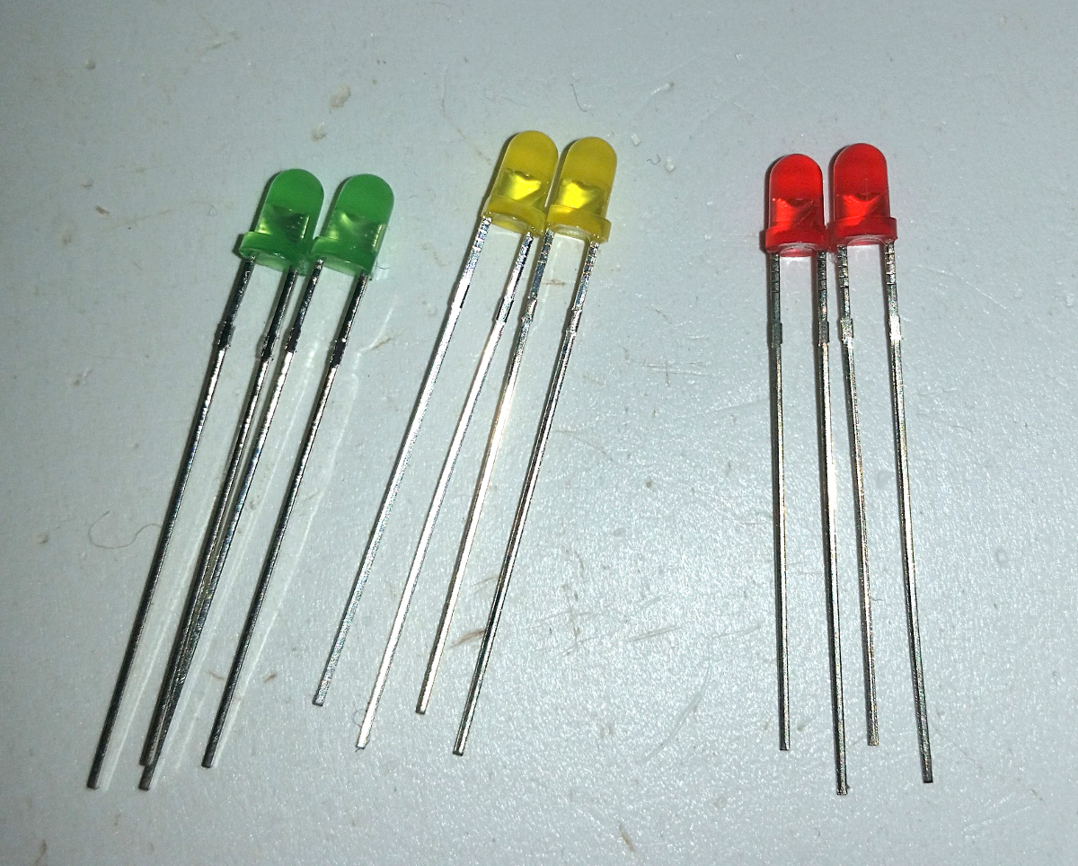
You’ll see the LEDs have one long and one short lead. The long is the + (positive) side, short is – (negative). To make it easy to remember:
+ is more, – is less.
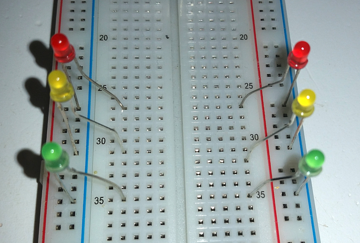
LEDs only let electricity flow through in one direction, so when you connect them on the breadboard, make sure the short lead goes to the negative power rail (with a blue line) and the long lead goes to the A and J column in the middle part of the breadboard. Repeat this for each colour, red, yellow and green. Leave 3 empty rows between the LEDs, to avoid squashing them too close together, and to leave some space for the connections we’ll have to make.
Repeat on the other side of the breadboard as well.
Resistors
Next up, resistors.
The LEDs have a limit to the amount of electrical current they can pass. 20mA (milli-Amps) is the usual limit. Try to pass more than this and they will burn out, either immediately or within seconds. Another consideration is the current limit of the microcontroller. Most Arduinos and compatible have a limit of max 20mA per pin, and the Pro Trinket has a limit of max 150mA for the whole chip.
To limit the current flowing through the LEDs, we use resistors. Imagine a water hose, the harder you squeeze (higher resistance, higher Ω-value), the less water will flow through. (Lower current, lower A-value) To calculate which resistor values we need, we’ll need to know the “forward voltage” of the LEDs. This is available on the datasheet for the LEDs, but if you don’t have that, the following are some guidelines based on the colour:
- Red – 1.8V
- Yellow – 2.1V
- Green – 2.3V
- Blue – 3.0V
- White – 3.1V
According to Kirchhoff’s voltage law, we need to “dispose of” the 5V we are putting into the circuit. The LED takes care of some of it, as identified by its forward voltage.
For the red LED, the forward voltage is 1.8V, which leaves us with (5.0-1.8) = 3.2V remains. According to Ohm’s law, 20mA current and 3.2V gives:
, so
.
Repeating for the other colours, we get yellow, , and green,
.
So we have resistor values of 160Ω, 145Ω and 135Ω, respectively. These are what would pass 20mA, which is the absolute maximum current for the LEDs. However, a quirk of LEDs is that it is difficult to see the difference between small current changes close to the high end of the current range. The eye is much more sensitive to differences at the bottom end of the range, so we will restrict current a bit more and choose resistor values that are higher than these. 220Ω is a very common resistor value, and choosing that for all of them is a good starting point, and it makes sourcing parts for the project a lot easier. It also makes it a lot easier to stay within the total power budget for the microcontroller.
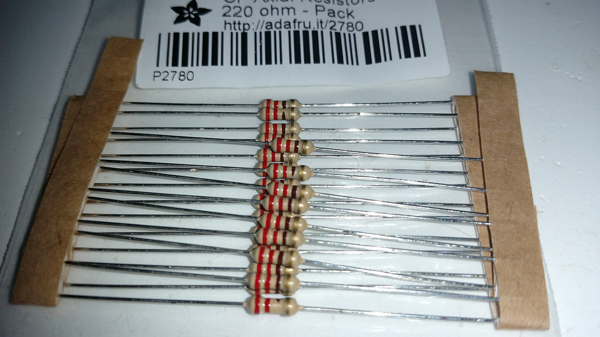
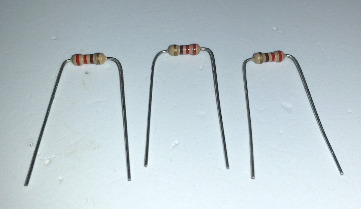
Axial resistors usually come in strips of varying lengths, called bandoliers. Get 6 resistors and bend the leads as shown below. Easiest way: Put your thumb nail on the lead just to the side of the resistor and use the fingers of your other hand to bend the lead 90°, then turn the resistor around and do the same on the other side. The coloured bands on the resistors show the resistance. There are several references to these colours, one of them is here. Red-Red-Black means 220Ω.
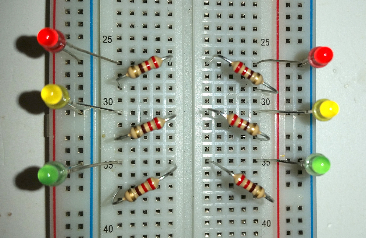
Insert the resistors into the breadboard with one lead opposite the LED’s long lead (E and F columns) and the other lead to the A and J columns, 2 rows down.
Jumper wires
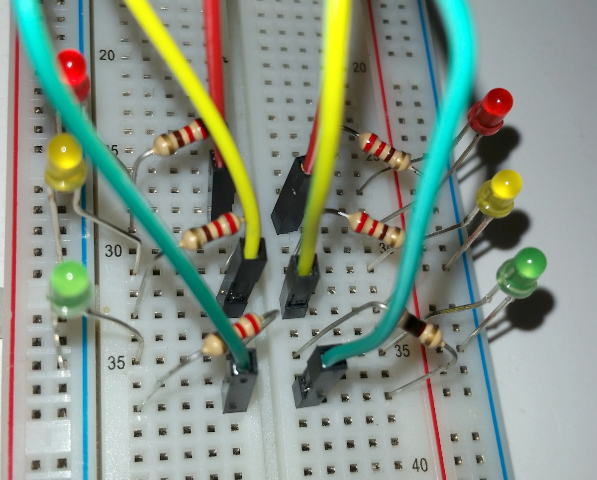
The final step of the hardware build is to install jumper wires to connect the LEDs to the microcontroller. This is where things may end up looking different if you are using a different microcontroller.
You’ll hook up the red LEDs first. Start by inserting one end of the jumper wire into the row where the resistor from the red LED goes. It can be plugged anywhere on the row, but to make the circuit look neater, use the E/F columns. The other end of the wire goes to the microcontroller’s pin number 9 (for the left side) and 8 (for the right side).
Yellow is hooked up the same way, but to pin 10 (left) and 6 (right).
Green goes to pin 11 (left) and 5 (right).
If your microcontroller is different, connect the wires to the points that have the same numbers as shown here. By using the same numbers, you will make sure the sketch will work without modifications.
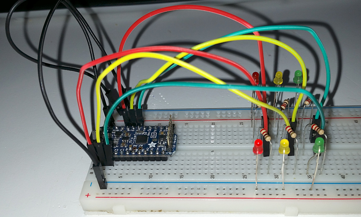
I have chosen wire colours matching the LED colours, to make it easier to see and understand, but feel free to choose whatever colours you want.
That’s the LEDs taken care of. All that remains now is to connect ground to complete the circuit. The microcontroller has a pin labelled simply as “G” (other controllers may have “GND”). connect a wire from the hole just next to this pin and to the negative power rail (“-” and a blue line). This connects the ground for one side of the circuit.
The final wire goes from one of the negative power rails to the one on the other side of the breadboard. This connects ground for the other side as well. I have chosen black wires as a convention for ground. You can choose your own colours, but following convention is a good habit.
The circuit is now finished, and should look like this:
In the next part, I will introduce the sketch to drive this circuit.