

Welcome back.
In the previous part, I showed you how to connect the circuit for the traffic lights simulator. This time, I’ll show you the sketch to control them.
If you do not have the Arduino software installed already, it can be downloaded from the Arduino website. You’ll need the Arduino IDE, I have not tested any of this with the Online IDE.
To start, create a new sketch. First, at the top of the sketch we’re going to add some defines to tell the compiler which pins we are using for the LEDs. This lets us refer to the pins by name, rather than number. This way, if we change the pin numbers, there’s only one place to change, rather than all over the code.
#define RED_RIGHT    8
#define YELLOW_RIGHT 6
#define GREEN_RIGHT  5

#define RED_LEFT    9
#define YELLOW_LEFT 10
#define GREEN_LEFT  11
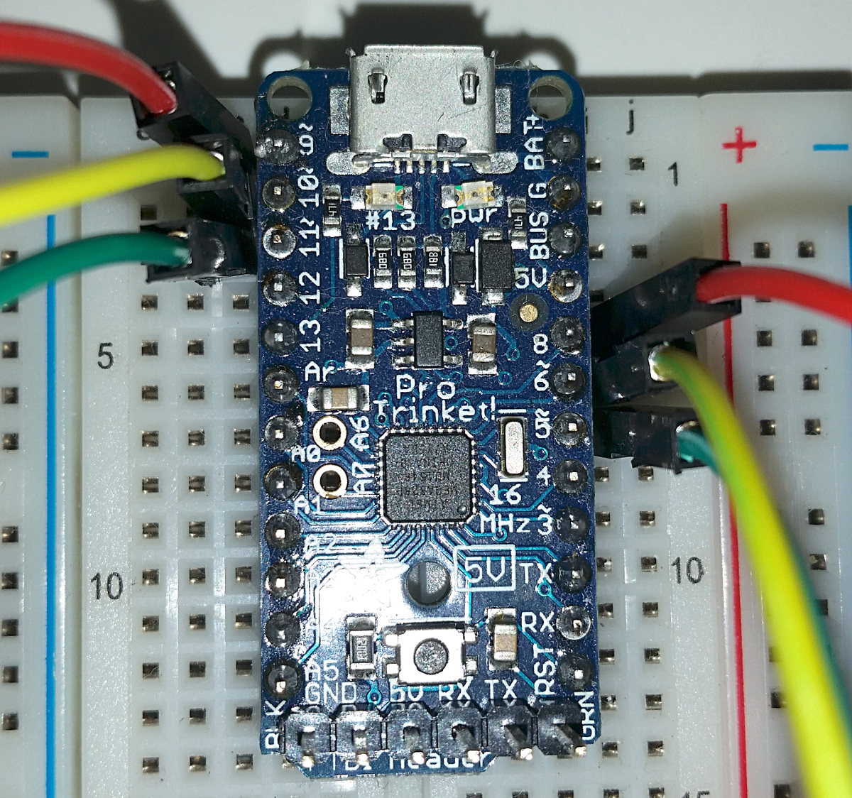
Review the previous part and confirm that your circuit have the LEDs connected to the pins shown:
The setup() function contains code that is run once, when the microcontroller starts. We’re starting by configuring the 6 pins we’re using as outputs. Once the pins are configured as output, we can switch an LED on by writing a HIGH to it, and off by writing a LOW. To make sure the LEDs are all in a known state when the sketch starts, we’ll set them all to LOW.
void setup() {
  // Configure the LED pins as outputs
  pinMode( RED_RIGHT, OUTPUT );
  pinMode( YELLOW_RIGHT, OUTPUT );
  pinMode( GREEN_RIGHT, OUTPUT );
  pinMode( RED_LEFT, OUTPUT );
  pinMode( YELLOW_LEFT, OUTPUT );
  pinMode( GREEN_LEFT, OUTPUT );

  // Make sure all LEDs are off when the sketch starts
  digitalWrite( RED_RIGHT, LOW );
  digitalWrite( YELLOW_RIGHT, LOW );
  digitalWrite( GREEN_RIGHT, LOW );
  digitalWrite( RED_LEFT, LOW );
  digitalWrite( YELLOW_LEFT, LOW );
  digitalWrite( GREEN_LEFT, LOW );
}
After the setup() function has completed, the microcontroller will run the loop() function over and over again until it is powered down. For a cyclical operation like a traffic light, we can let the loop() function take care of one cycle and it will automatically start the next cycle as soon as it reaches the end of the function.
The first step is to set the right channel to red and left to green. Then we’ll tell the microcontroller to wait for 15 seconds.
void loop() {
  digitalWrite( RED_RIGHT, HIGH );
  digitalWrite( GREEN_LEFT, HIGH );
  digitalWrite( RED_LEFT, LOW );
  delay( 15000 ); // Left green, right red, 15 seconds
Don’t worry about the RED_LEFT being set to LOW, that’s there to help the transition from the end of the cycle back to the beginning.
Next, after the 15 seconds are up, the left channel will go yellow for 3 seconds. Notice that we’re not setting every pin every time, we’re only setting those pins that change.
 digitalWrite( YELLOW_LEFT, HIGH );
 digitalWrite( GREEN_LEFT, LOW );
 delay( 3000 ); // Left yellow, 3 seconds
Now it’s time to set the left channel to red, but we can’t give the right channel the green light just yet. We’ll keep both on red for 2 seconds.
 digitalWrite( RED_LEFT, HIGH );
 digitalWrite( YELLOW_LEFT, LOW );
 delay( 2000 ); // Both red, 2 seconds
Then it’s finally time for the right channel to get the green light for 15 seconds.
 digitalWrite( RED_RIGHT, LOW );
 digitalWrite( GREEN_RIGHT, HIGH );
 delay( 15000 ); // Left red, right green, 15 seconds
Next, the right channel goes to yellow for 3 seconds.
 digitalWrite( GREEN_RIGHT, LOW );
 digitalWrite( YELLOW_RIGHT, HIGH );
 delay( 3000 ); // Left red, right yellow, 3 seconds
And just as earlier, we keep both channels on red for 2 seconds.
 digitalWrite( RED_RIGHT, HIGH );
 digitalWrite( YELLOW_RIGHT, LOW );
 delay( 2000 ); // Both red, 2 seconds
}
And as we reach the end of loop(), the microcontroller will start from the top again. Hence why we needed to set the left red LED to LOW in the first part of the cycle, otherwise it would stay on as the green LED comes on.
That’s all. Compile the sketch and upload it to the microcontroller.
The full sketch can be downloaded from here: trafficlights.zip
In the next part, I’ll show how to use a push button to control the cycling of the traffic lights and I’ll also introduce the concept of state tables.