

Recently, I added solar power to one of my ESP8266 weather stations.
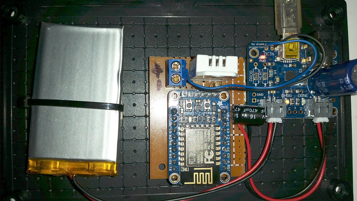
With the right hardware, this was actually remarkably easy to do. To make things nice and easy, I ordered an Adafruit USB/DC/Solar Li-Ion/Li-Poly charger. (Top-right in the photo) These boards can take DC input from USB, a 2.1mm power jack or from wires soldered directly onto the board. It will then both charge a Li-poly battery and power a load. Whatever power is left over from powering the load will be used to charge the battery, and if the load draws more than what the solar panel can provide, the rest will be drawn from the battery.
The charger is designed for 6V solar panels, but unfortunately I didn’t have access to any 6 volt panels. I did, however, have a few 1.5V, 500mA panels, and connected 4 of them in series to get a 6 volt array.
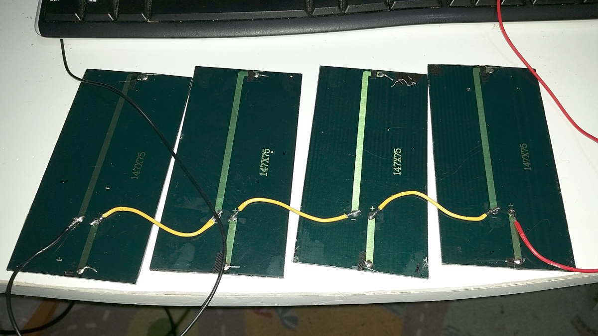
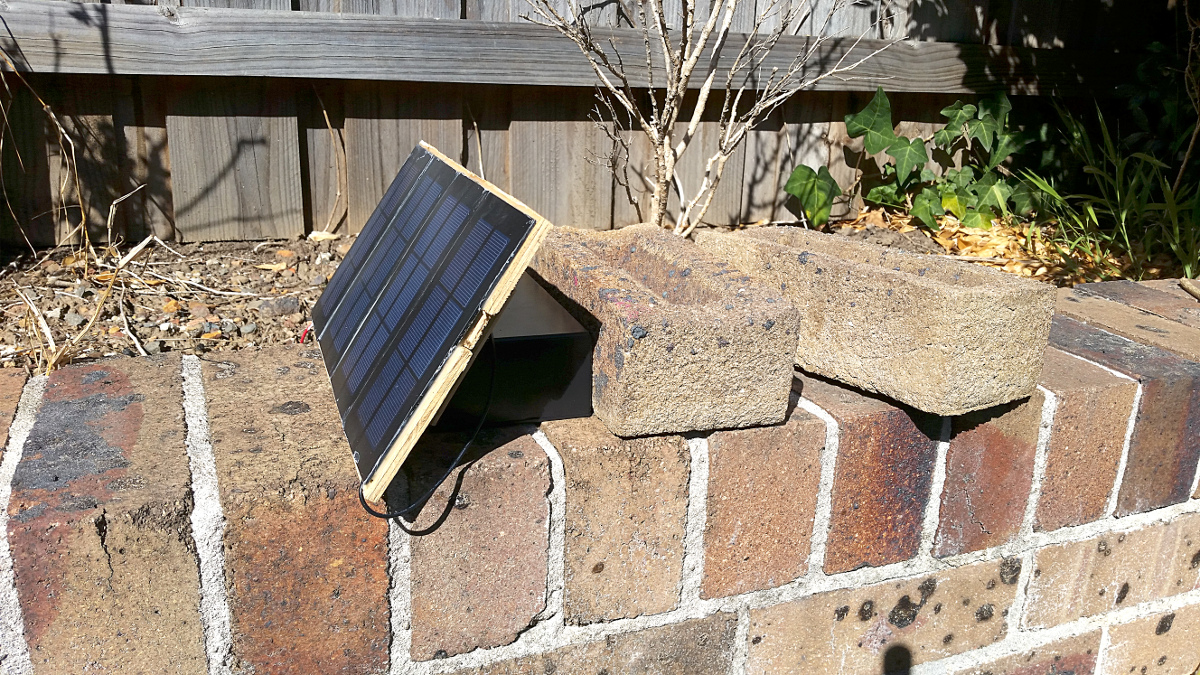
The panels were mounted on some spare plywood, with all holes covered and wiring protected by epoxy glue. I’ll give the plywood some coats of clear as well, before I start leaving this outside, to reduce the chances of water getting in behind the panels.
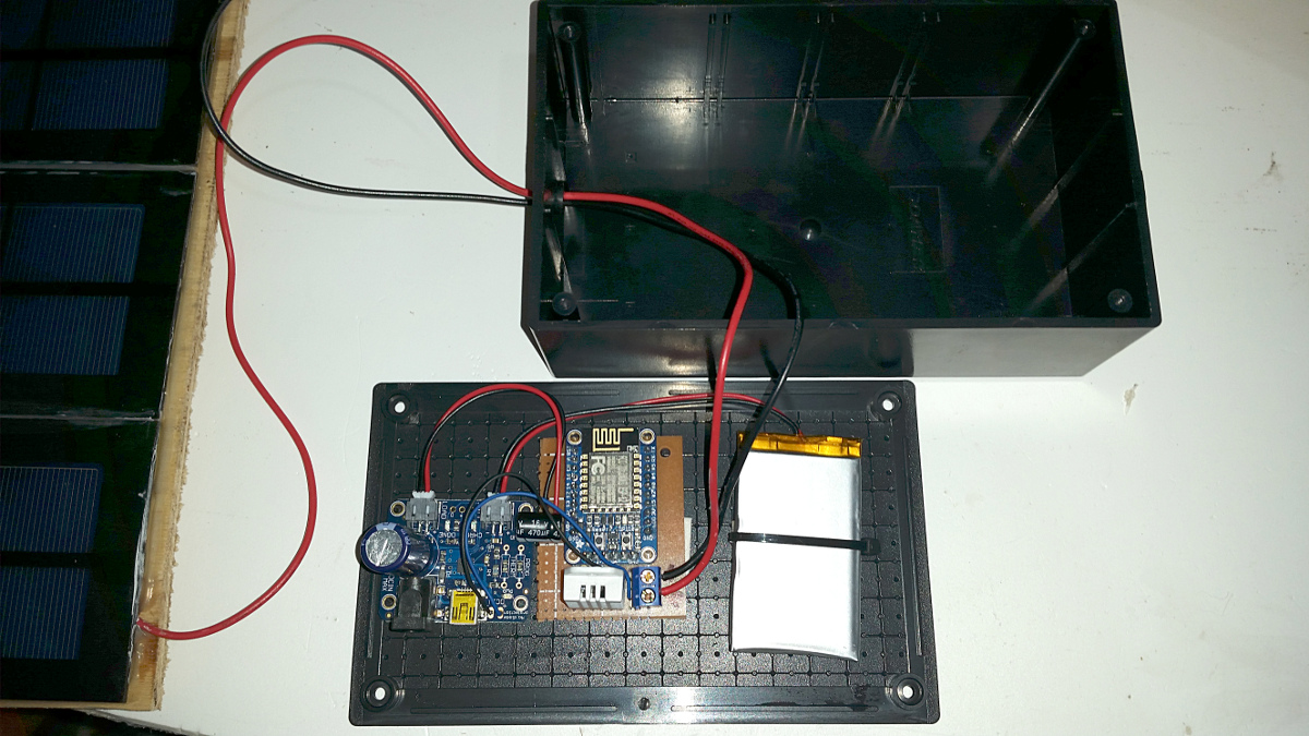
I ran the wires through a hole in the side of the weather station enclosure, with a grommet inserted to reduce wear and tear on the insulation.
I will be changing solar panels in the future as I experiment with different panel sizes (frankly, this one is too huge, and looks like something only its creator might love) so the wires are terminated in a screw terminal, from where I run a short set of hookup wires to the charger board.
The battery is connected to the board through a JST connector marked BATT, and the weather station board is connected through another JST connector marked LOAD. The battery itself is just loosely held in place by a cable tie, so I can easily remove and replace it, as I experiment with different battery sizes. (Loose enough that the battery is not damaged)
So, how does it perform?
With a panel like that, I’d expect it to perform quite well, and indeed it does. Even when the weather station is configured to wake up and report over WiFi every 30 seconds, the panel is still able to keep the battery topped up every day. It will struggle a bit after a week of rain and overcast, so I have reduced the reporting rate to once every 2 minutes. That’s still a lot more frequent than my other weather stations which report every 5 minutes. This graph shows the measured supply voltage over 6 days.
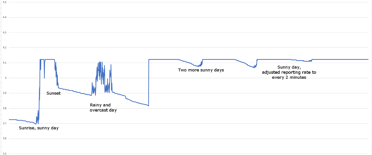
Unfortunately, the 180KΩ/56KΩ voltage divider I had on this particular board was not particularly suited for a solar panel and Li-Poly battery scenario. The resulting ~4.2x divider was meant for 3xNiMH cells. During bright sunshine, the supply voltage will reach 6V, but you can seethis detail is being clipped in the graph above, with the reported voltage topping out at 4.2V.
I have replaced the high-side resistor with a 330KΩ, which gives a new division ratio of ~6.9x and will update this post when I have a few days of new readings.
A word of caution
Batteries containing lithium need to be treated carefully. If they are damaged, short circuited, overcharged, overheated, frozen, or even just sweared at, they are likely to catch fire.
Before you use such batteries, make sure your batteries will be treated properly, i.e. your circuits are safe, that the batteries are not overcharged or overheated, etc.
What I have shown here worked for me, but you’ll need to do your own due dilligence on your own setup.
hi
can you post the schema please?
the capacitor 470 uF where’s attached?
thanks
Hi.
Sorry for the delay, but my day job is taking more than its fair share of my attention these days.
I will publish the schematics as well as the source code eventually, just need to finish some work projects first, before I will have time to finish that post (and others).
The capacitor is attached as close as possible to the VBat and GND pins from the ESP8266 module. I have mounted the module on a proto board (perf board), and the capacitor is mounted in the next holes over. The legs of the capacitor have been connected directly to the VBat and GND pins.
In the image, you can see the ESP8266 module on the perf board, the capacitor in the next row of holes, and then the power and ground from the power supply in the next row after that (hidden behind the capacitor).